| Nonoz III DAC | ||||||||||||||||||||||||||||||||||||||||||||||||||||||||||||||||||||||||||||||||
Updated on: July 3rd 2007 |
||||||||||||||||||||||||||||||||||||||||||||||||||||||||||||||||||||||||||||||||
|
For the past months, I have been busy with experiments to improve the Nonoz II DAC.
This has resulted in the Nonoz III DAC. I have the feeling that some parts of the Nonoz III can be improved and tuned. Still, I think that
the current version is worthy of a release. In the next months, I'll see what improvements can be made... It is now time to reveal the schematics of the DAC: show me the Nonoz III!!! In the schematic, I included the Nonoz I S/P-DIF input configuration without transformer. The circuit with transformer I use now at the RXN and RXP pins of the receiver is borrowed from the Marc Heijligers DAC page. |
||||||||||||||||||||||||||||||||||||||||||||||||||||||||||||||||||||||||||||||||
| FAQ | ||||||||||||||||||||||||||||||||||||||||||||||||||||||||||||||||||||||||||||||||
|
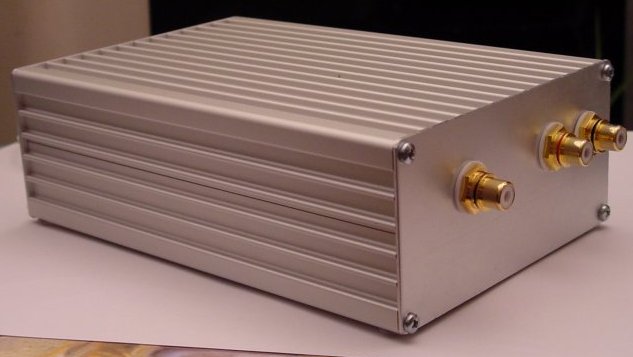
What is the difference with the Nonoz II? The Nonoz III has even less parts than the Nonoz II. The output level of the Nonoz III is much higher due to the larger I/V resistors. The supply is simpler and I got rid of the pre-regulator. Which Nonoz DAC sounds the best? IMHO, the Nonoz III sounds the most accurate of all. It has better dynamics, more detail and maybe is even a bit smoother than version I and II. Why didn't you include the S/P-DIF transformer in the schematic? I think that many DIY-ers will first build the DAC without S/P-DIF transformer. It easy to build in a transformer later. Also, the circuit to be used depends on the type of S/P-DIF transformer. That's a nice PCB, can I buy it from you? At this moment, no. The PCB is designed by Jean-Paul and I do not have the masks to make them. Regrettably, the design has been lost in a harddisk crash :-( We will work towards a solution for this problem. In the meantime, you can buy PCB's from Doede Douma. It should be possible to fit a large part of the Nonoz III circuit on his PCB. How does the Nonoz III DAC compare to the DDDAC1543? I did not build that DAC yet, so I have no idea. I hope to hear one next year! Why are there two 4.7 uF capacitors in parallel in the schematic? This is the Super-E configuration. This means that two Black Gate capacitors are placed in anti-parallel position. The orientation of the Black Gate caps can be observed by looking at the texts. What is R7 in the schematic? I use a 2k resistor with a 10k variable resistor in parallel. R7 has to be adjusted for 4.4 Vdc on the output caps (C11-C14). Why don't you use reclocking anymore? This has multiple reasons. First of all, I wanted to make the DAC as simple as possible, to be able to build it on a small PCB and to make it more accessible for DIY-ers. Also, I had problems to get the reclocked DAC silent. After all, it is maybe not a good idea to build 100 Mhz circuits on experimental PCB's... (though good shielding will solve a part of the problems) What supply do you use? I use a 2x15VAC, 15VA toroid. The DC voltage at the DAC is 21V. The regulators get hot, but it works ok. I use a 200 mA fuse in series with the primary. Furthermore, I use a netfilter. I suggest to use a 12VAC or 10.5VAC transformer. Can I use a battery? Sure! It is a good plan to use a battery. You can use 1x12V, 2x6V or even 3x6V... Where can I get the aluminium cases? You can get them from Conrad. The part number is 522945. I payed EUR 13,27 for one. What does the Nonoz III cost to build!? I did not calculate that yet. I'd guess between 60 and 130 euro, depending on the build quality. Gee, where do you get your inspiration? A large part of this DAC is inspired by the Shigaraki DAC of 47 Labs made by Kimura. Though it is certainly not an exact copy of that DAC! If you want the exact sound of the Shigaraki DAC, buy one! If you want a DAC that comes relatively close in performance and costs far less, build the Nonoz III ;-) Why are there no photos on this page? Because they have not yet been made. See the Nonoz II photos to get an idea of the looks: Picture1 Picture2 Is this the end of the FAQ? Yes it is. |
||||||||||||||||||||||||||||||||||||||||||||||||||||||||||||||||||||||||||||||||
| DIY!!! | ||||||||||||||||||||||||||||||||||||||||||||||||||||||||||||||||||||||||||||||||
| Try building this DAC yourself ! You can have a lot of fun. Here are some general guidelines: |
||||||||||||||||||||||||||||||||||||||||||||||||||||||||||||||||||||||||||||||||
| Datasheets | ||||||||||||||||||||||||||||||||||||||||||||||||||||||||||||||||||||||||||||||||
|
|
||||||||||||||||||||||||||||||||||||||||||||||||||||||||||||||||||||||||||||||||
| Parts list | ||||||||||||||||||||||||||||||||||||||||||||||||||||||||||||||||||||||||||||||||
|
||||||||||||||||||||||||||||||||||||||||||||||||||||||||||||||||||||||||||||||||
| Links | ||||||||||||||||||||||||||||||||||||||||||||||||||||||||||||||||||||||||||||||||
|
47 Labs, the company that makes very inspiring audio designs! Amp Chip DIY forum, forum about Gainclones and non-oversampling DACs Doede Douma's page, you can find the DDDAC1543 project here Audio-cube, page about 47 Labs and other high-end products RJM DAC page, the non-oversampling DAC of Richard Murdey Scott Nixon's DAC page, the non-oversampling DACKIT PCBs can be bought here |
||||||||||||||||||||||||||||||||||||||||||||||||||||||||||||||||||||||||||||||||
|
Show the other audio projects please!!! |